Yılmaz Defense Industry

KEM 200

/

Cartridge Case Gauging Machine

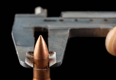
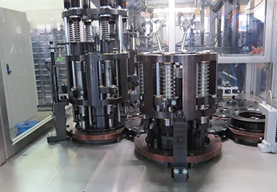
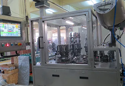
It starts with the feeding of the cartridge cases, which have been channeled, cut to the final length and chamfered, to the machine with the automatic feeding unit. The machine operates with cam systems and gear systems. Control points on the cartridge case are completed physically and by means of the sensors at separate stations respectively.
The following control procedures will be carried out during the dimensional inspection. All checks other than the presence of the flame hole will be carried out using a physical gauge.
  1. Max. and min. total length of the cartridge case,
  2. Maximum and minimum rim nail diameter,
  3. Maximum and minimum nail groove diameter,
  4. Existence of flame hole,
  5. Rim nail thickness maximum and minimum values,
  6. Depth of primer pocket,
  1. Length of gunpowder filling chamber,
  2. Inner mouth diameter,
  3. Max. and min. primer pocket diameter,
  4. Controlling overall form of cartridge case,
  5. Max. and min. thickness of primer pocket depth,
The bench will check whether the dimensions of the inputs comply with the tolerances given in the technical drawings and will separate the faulty inputs. It will eject the entries that it detects to be incorrect into the reject boxes. Incorrect entries will be ejected to separate boxes according to their error criterias.

MACHINE LAYOUT PLAN

TECHNICAL SPECIFICATIONS

Product

Cartridge Case

Capacity

200 pcs / min.

Avg. Electricty Consumption

3 kW

Installed Electrical Power

6 kW

Compressed Air Consumption

6-7 Bar NI / min. (Free From Oil and Dust)

Noise Level

Maximum 85 Decibels (According to ISO EN 11688-1)

Output Product Formats

5,56 - 7,62 mm Necked Maneuver Cartridge Case 7,62 mm x (51-39) Cartridge Case

Facility Field Conditions

Dust Free and Maximum 70% Relative Humidity

Product Material

CuZn30

Labor Requirement

1 Operator / Shift

Lubrication System

Automatic Lubrication System

Feeding System

Silo and Optional Conveyor System